TL494 Class D Amplifier SMPS 390W 32V – Electronics Projects Circuits: Expert Design Tips! Smps circuit diagram for audio amplifier
Alright, let's dive into a couple of interesting circuit designs I stumbled across recently. Been tinkering with audio amplifiers lately and these sparked my interest. It's always fascinating to see how different engineers approach the same problem – getting that crystal-clear sound at a decent power level.
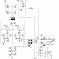
Class D 500W Amplifier Schematic

This first one is a Class D amplifier, purportedly capable of pushing 500 watts. That's quite a bit of power! Now, Class D amplifiers are known for their efficiency, which is crucial when dealing with higher power applications. Less heat, longer component life, and all that good stuff. Looking at the schematic, it appears to utilize a NE5532 op-amp as a preamplifier or signal conditioner, followed by an IR2184 gate driver IC, and then a set of KNP9120 MOSFETs for the final output stage. The NE5532 is a solid choice for audio applications, known for its low noise and decent bandwidth. The IR2184 is a standard gate driver, ensuring the MOSFETs switch cleanly and efficiently. The choice of MOSFETs is also key; the KNP9120 needs to be robust enough to handle the high current demands of a 500W amplifier, and also switch quickly to minimize switching losses. What really catches my eye is the complexity of the feedback network. Fine tuning the feedback loop in a Class D amplifier is vital. This part will ensure that the amp is stable and distortion is minimum. I'd be curious to see the actual performance metrics of this design; things like Total Harmonic Distortion (THD) and Signal-to-Noise Ratio (SNR) would be crucial in evaluating its audio quality. Proper heat sinking is essential for all these components, of course. That's the reality that often gets glossed over in these circuit diagrams, but it's critical for long-term reliability.
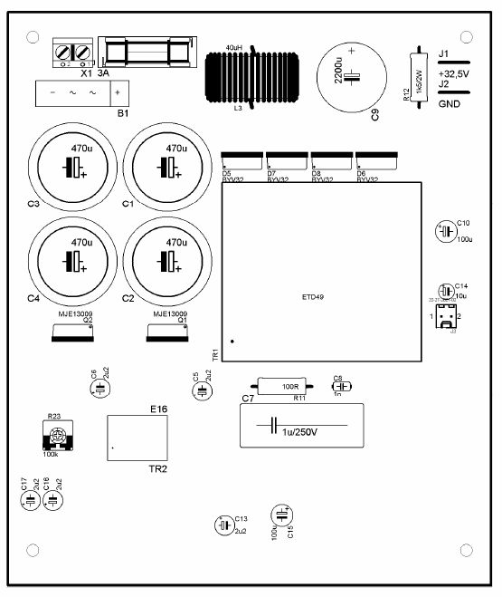
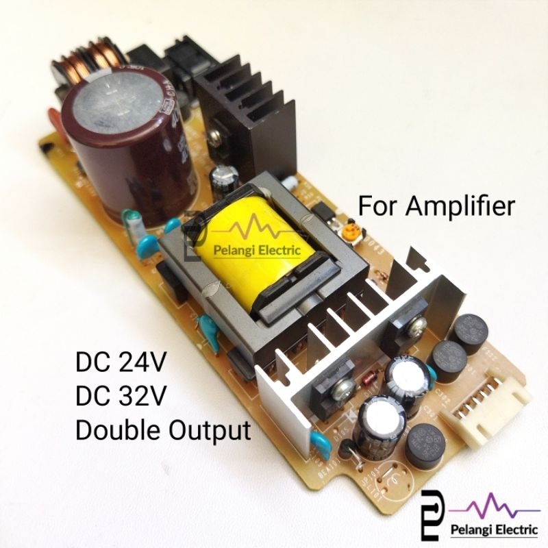
SMPS for Audio Amplifier Circuit

Moving on to the second image, we have a Switch-Mode Power Supply (SMPS) specifically designed for an audio amplifier. This is interesting because powering a high-power audio amplifier efficiently is often a significant challenge. Traditional linear power supplies can be bulky and inefficient, especially when you need to deliver a clean, stable voltage under varying load conditions. SMPSs, on the other hand, offer much better efficiency and can be significantly smaller and lighter. This particular one seems to be designed for car audio applications, judging by the DC-DC conversion. This likely means it's taking the 12V from the car's battery and stepping it up to a higher voltage suitable for powering the amplifier. The PCB layout is quite dense, which is typical for SMPS designs. Proper layout is absolutely critical to minimize noise and EMI (Electromagnetic Interference), which can wreak havoc on audio quality. You'll notice the careful placement of components to minimize loop areas and keep high-current paths as short as possible. The use of large capacitors for filtering is also evident, ensuring a stable and clean output voltage. Key features that would be vital in a real application includes over-voltage protection and overload protection. These safeguards are essential to protect the power supply and the amplifier from damage in case of faults. Overall, this looks like a well-designed SMPS, purpose-built for the demands of car audio. It's a testament to the engineering involved in creating high-quality sound systems, even in challenging environments like a car.
If you are searching about 1200W 60V SMPS Circuit UC3844 150Khz – Electronics Projects Circuits you've came to the right place. We have 25 Pictures about 1200W 60V SMPS Circuit UC3844 150Khz – Electronics Projects Circuits like 1200W 60V SMPS Circuit UC3844 150Khz – Electronics Projects Circuits, circuit-schematic-class-d-500w-amplifier-ne5532-ir2184-knp9120-mosfet and also Smps For Audio Amplifier Circuit. Read more:
1200W 60V SMPS Circuit UC3844 150Khz – Electronics Projects Circuits
 www.pinterest.com
 Smps Circuit Diagram For Audio Amplifier
 www.circuitdiagram.co
 Tl494 Class D Amplifier Circuit Diagram
 www.circuitdiagram.co
 TL494 Class D Amplifier SMPS 390W 32V – Electronics Projects Circuits
 320volt.com
 smps amplifier tl494 circuit class
Smps For Audio Amplifier Circuit
 www.circuitdiagram.co
 TL494 Class D 500 Watt Amplifier PCB Layout & Schematic
 technicalmriganka.myinstamojo.com
 Tl494 Class D Amplifier Circuit Diagram
 www.circuitdiagram.co
 Circuit-schematic-class-d-500w-amplifier-ne5532-ir2184-knp9120-mosfet
in.pinterest.com TL494 Class D Amplifier Circuit 500w Amplifier, 47% OFF
 americanprime.com.br
 TL494 Class D Amplifier SMPS 390W 32V – Electronics Projects Circuits
 320volt.com
 Tl494 Class D Amplifier Circuit Diagram
 www.circuitdiagram.co
 Smps For Audio Amplifier Circuit
 www.circuitdiagram.co
 TL494 Class D Amplifier SMPS 390W 32V – Electronics Projects Circuits
 320volt.com
 TL494 Class D Amplifier SMPS 390W 32V – Electronics Projects Circuits
 320volt.com
 tl494 smps amplifier pcb 390w 32v class
Tl494 Class D Amplifier Smps 390w 32v – Artofit
 www.artofit.org
 Tl494 Class D Amplifier Smps 390w 32v – Artofit
 www.artofit.org
 [DIAGRAM] Class D Amplifier Circuit Diagram - MYDIAGRAM.ONLINE
![[DIAGRAM] Class D Amplifier Circuit Diagram - MYDIAGRAM.ONLINE](https://solderingmind.com/wp-content/uploads/2019/07/TL494-class-D-amplifier-1.jpg) mydiagram.online
mydiagram.online Power Supply Smps 24V 32V 10A Non CT Double Output For Amplifier Class
 shopee.sg
 Smps Circuit Diagram For Audio Amplifier - Circuit Diagram
 www.circuitdiagram.co
 Class D Amplifier Circuit Design
 all-audio.pro
 Smps For Audio Amplifier Circuit
www.circuitdiagram.co Switching Amplifier Class-D TL494 | DiyAudio
Smps For Audio Amplifier Circuit - Circuit Diagram
 www.circuitdiagram.co
 Diy Test Power Amplifier Tl494 Class D Mosfet N Channel Very Old Class
 www.artofit.org
 Smps For Audio Amplifier Circuit - Circuit Diagram
 www.circuitdiagram.co
 Circuit-schematic-class-d-500w-amplifier-ne5532-ir2184-knp9120-mosfet. Tl494 class d amplifier smps 390w 32v – artofit. Tl494 class d amplifier smps 390w 32v – electronics projects circuits